

A joint on an aerial span and a joint in a duct are not the same purchase. The aerial closure hangs from a messenger under wind and thermal cycling. The duct closure sits where water drains and where a crew can still reach it. The closure at a heavy branching point has to hold a splitter as well as splices. The Fiber Optic Association's closure guidance puts the number of cables, fibers and splices first, then the location of the closure, then special needs such as internal splitters, and treats ruggedness and sealing as the primary concern. FOA, Fiber Optic Splice Closures This article follows the same order: laying method and mounting first, capacity second, port and cable fit third, branch function fourth, re-entry fifth. The IP rating comes last, because it is the one line on a datasheet that most often turns out to be less than it looks.
Start with the mounting condition, not the closure name
The closure's installation line is the hardest constraint on a route. It decides whether the splice can be reached at all, and what the seal has to survive. The range offered here divides along that line fairly cleanly.
- Overhead or duct, straight-through joints. The Horizontal Optical Cable Joint Box lists overhead and pipeline installation and uses a mechanical seal. The Horizontal Dual-End Optical Cable Joint Box covers the same two mounting cases at higher capacity.
- Manholes, poles and walls. The Cap-Type Optical Cable Joint Box lists wall, pole and manhole mounting. Entries gathered at one end make a closure easier to handle when a crew has to coil service loops inside a manhole or under a pole. FOA describes the single-end (dome or butt) form as the more popular one and notes that its single end seal can be the more reliable sealing pattern. Inline construction, with entries at both ends, is the choice FOA ties to splicing two identical cables where space or a repair favours it.
- Wall and pole. The Special-Type Optical Cable Splicing Box lists wall and pole mounting only.
- Overhead, duct or buried, plus FTTH branching. The Multi-Branch Optical Cable Joint Box lists wall-mounted, pipeline, overhead and buried applications.
The list above is each model's own Installation Methods line. Several of these pages also open with a shared paragraph naming overhead, pipeline and direct-burial use; where the two differ, the model line is the narrower and specific one.
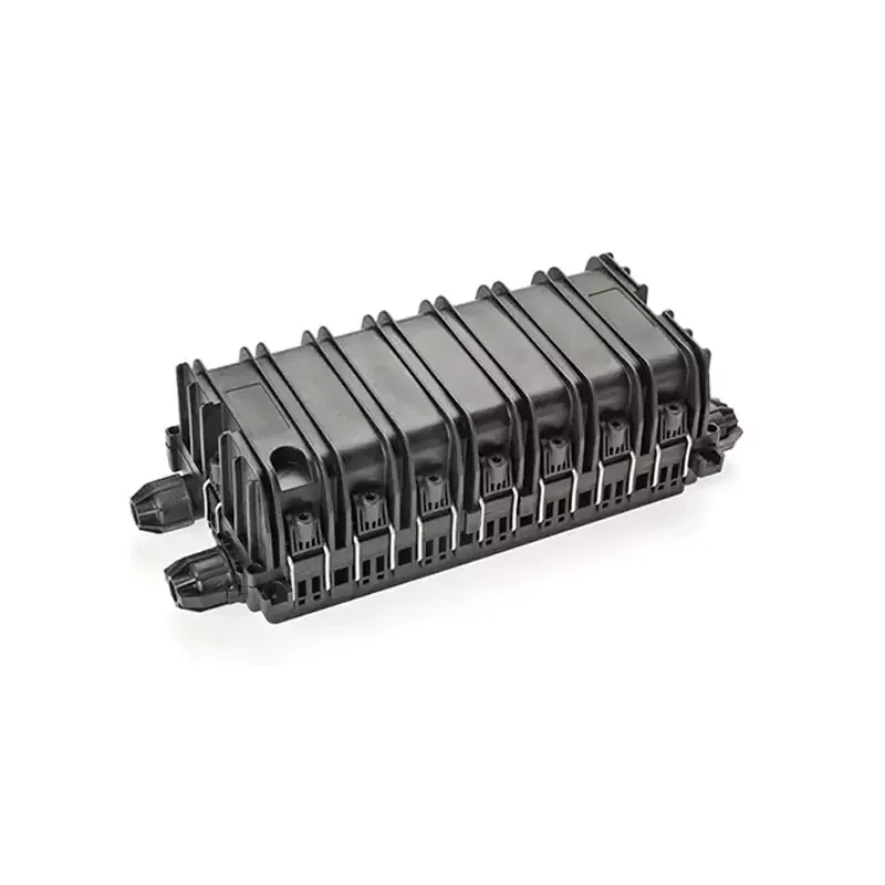
Whichever method is selected, two site conditions belong in the same decision. The closure has to be fixed according to its installation type, and the spare cable has to be coiled where it will survive. That means inside a handhole or manhole, on a wall fixture indoors, or lashed to the messenger on an aerial run. FOA's installation notes require that coil to stay within the cable's minimum bend radius. The space for that loop sits next to the closure, not inside it, so a workable coil has to be confirmed before the core count is fixed.
Fix capacity from the tray build, then the core count
Maximum core count is a multiplication, and the multiplier matters more than the total. Each of these closures is described by a tray size and a tray count, and the maximum exists only in the configuration the page states.
The horizontal dual-end box is the clearest case. It supports six 24-core trays or 144-core trays, giving a maximum of 864 cores. The 864 figure depends on the 144-core trays. Six 24-core trays in the same body hold 144 cores. Two configurations therefore exist for one box, and a purchase order that asks for "864-core capacity" without naming the tray type is asking for one of the two. The special-type box follows the same pattern at smaller numbers: 12-core trays, up to twelve of them, 144 cores maximum.
Below that sit the 72-core builds, and there are two of them. The Horizontal Optical Cable Joint Box takes three 24-core trays. The Dual-End Optical Cable Joint Box takes the same three trays in a longer body, so it reaches the same 72 cores with more room. The six-tray 864-core body is the Horizontal Dual-End box, a separate page from these two. For a straight-through splice at a lower core count, three trays are the whole requirement, and tray positions that will never be filled add volume to a span, a duct or a manhole for no benefit.
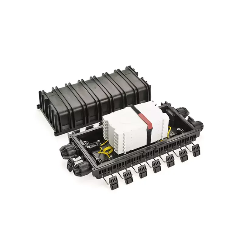
Project the count over the life of the route rather than to the day it is commissioned. Growth usually arrives as more splices in the same place: a new branch, a re-splice after damage, a spare tube brought into service. Each of those needs tray space, not just cores. A box chosen at exactly today's core count has no tray left for the next move.
Check ports and cable diameters against the real cable schedule
Port geometry is where selection most often fails in practice, because it gets checked against a fibre count rather than against the cables that will actually enter.
The two horizontal boxes have four cable ports, two inlets and two outlets, sealing optical cable from Φ10 to 18 mm. That is a straight-through and branch pattern for four cables at a joint. The multi-branch box works differently: six round inlet and outlet pipes of Φ20 mm, sized for cable up to Φ20 mm as well as 2×3 mm and Φ5 mm drop cable. Six entries is the pattern that supports several distribution cables from one point. The special-type box splits its entries by function: one non-cut port for Φ10-17.5 mm cable, two branch ports for 6-8 mm and 10-17.5 mm cable, and six outgoing ports for round 6-8 mm cable. The cap-type box seals Φ10-17.5 mm cable and separates its cut port, which uses spin-press mechanical sealing, from its non-cut port, which uses direct-press sealing.
Two points decide whether a box fits. A 2×3 mm flat drop cable is far below the Φ10-18 mm range of a straight-through box; its entry has to be designed for small flat-profile cable, which is why the multi-branch box lists that profile separately from its round-cable range. And every port used is a port the closure cannot offer later: four ports consumed by four main cables leave nothing for a later branch without opening the closure again.
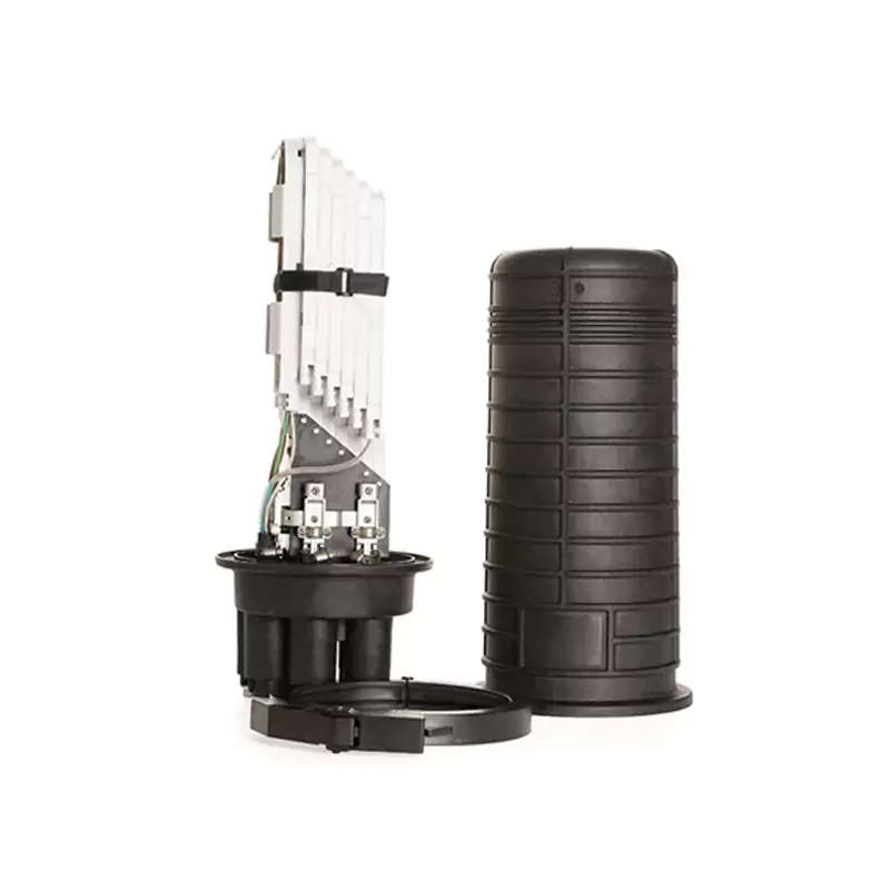
The cap-type box carries a single stated diameter range, Φ10-17.5 mm, where the horizontal boxes carry Φ10-18 mm. The two ranges overlap at 12 to 15 mm, so both pages list a cable of that size; whether a particular cable is accepted still depends on its jacket and on the closure's combined entry assembly. Above 17.5 mm only the horizontal boxes list a cable at all. The cap-type page also splits its sealing by port type: the cut port uses spin-press mechanical sealing, the non-cut port direct-press.
Add branching only when the closure has to split as well as splice
A closure that must also house the splitter is a different purchase from a closure that only splices, and both functions have to be confirmed in the same box. The Multi-Branch Optical Cable Joint Box accepts one 1:32 box-type PLC splitter inside. That single position sets a hard ceiling: one split point per closure, 32 outputs at the splitter, and the outgoing cables then have to fit within the six Φ20 mm pipes and their small-cable capacity.
The arithmetic that matters is the drop-cable count against the physical entries. Thirty-two outputs do not need thirty-two pipes. They need the outgoing pipes to carry the distribution cables, with drops landing on the ends that suit their profile. The stated range, round cable up to Φ20 mm plus 2×3 mm and Φ5 mm drop cable, is what tells a designer whether this pattern can serve the branch. If the branch needs a second splitter, or a higher split ratio in the same location, this box is the wrong unit; a separate splitter enclosure belongs in the design instead.
The splitter ratio is a system question, not a closure question. Loss for 1:N and 2:N ratios is published on the PLC splitter loss budget page, and the package this closure takes is described on the box-type optical splitter series page. Check the splitter's dimensions and mounting against the closure before ordering both.
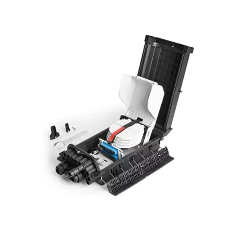
The open view shows the two fittings a branch closure has to carry at once: cable entry pipes gathered at one end of the body, and a module mounted beside the trays. The selection steps above rest on the pipe count and splitter position each page states, not on what a photograph shows. Where a decision turns on whether six Φ20 mm pipes accept a particular drop cable, or on how a box-type splitter mounts, ask for the mounting dimensions and the entry configuration in writing.
Weigh re-entry, because every closure will be opened again
The closure sealed once and never touched is unusual on a route. The realistic assumption is that every joint will be re-entered for a move, an add or a repair. FOA notes that closures get crowded and messy with additional cables over time and that entry for repairs becomes harder, which makes the opening mechanism a routine-work decision rather than a detail.
The horizontal dual-end box is built for it: a buckle design around the body enables screwless installation and re-opening. The cap-type and special-type boxes are described as re-openable, with mechanical sealing designed to be reused. The multi-branch box is described as compact and simple to operate, which matters when the closure is the working space for a splitter as well as splices.
A crew that removes and re-torques a set of fasteners at every re-entry pays in time and in the risk of a disturbed splice; a crew that lifts a buckle-off lid does not. Neither mechanism removes the re-seal check, because re-entering a sealed closure is exactly when the seal is most likely to be compromised. The mechanism decides how often that check happens at height or in a manhole.
Treat IP68 as a claim to be verified, not a specification to be copied
Every closure in this range carries IP68 in its feature list. The pages state the rating; they do not reference the standard it was assessed against, the laboratory, the test duration or the depth. That is normal for a product page, and it is not the same thing as a verified rating. Fix the claim in the document you will be judged against later, and let the evidence follow it.
What the code itself settles is limited. The IEC's own IP page describes the second numeral as a scale from 0 to 9 for liquid protection, and states explicitly that the full description of the ratings, including their testing conditions, is in IEC 60529. IEC, Ingress Protection ratings The standard is listed in its consolidated edition 2.2, with a publication date of 29 August 2013, and the edition matters when an acceptance document names one. FOA adds the second route: closures rated IP68 are assessed according to IEC 60529 or Telcordia GR-771-CORE, and GR-771 has not been updated since 2008.
What IP68 does not tell you is the part that matters on a buried or ducted joint: at what depth, for how long, and whether the closure was tested as delivered or after a realistic re-entry. If the project's acceptance criteria require a tested enclosure, the evidence has to address those conditions. FOA's installation guidance notes that sealed closures may need a pressure test. A soap solution is sprayed around the seams to look for leaks, the test pressure is released through the valve afterwards, and the inflation pressure and procedure come from the manufacturer's instructions. FOA closure guidance For a closure supplied with an air nozzle among its optional accessories, that is a test the site can run. Without one, the evidence has to come from the supplier.
On an aerial joint, the mounting and the re-entry mechanism carry most of the risk, and the design keeps the seal clear of standing water. On a duct or buried joint, water exposure is the ordinary condition, and a rating stated without conditions becomes the one line on the datasheet that has to be filled in before the closure is approved.
The range at a glance
| Closure | Listed installation | Capacity (trays × cores) | Cable ports and diameter range | Mechanism and re-entry |
|---|---|---|---|---|
| Horizontal Optical Cable Joint Box | Overhead, pipeline | 3 × 24-core, max 72 cores | 4 ports (2 in / 2 out), Φ10-18 mm | Mechanical seal |
| Dual-End Optical Cable Joint Box | Overhead, pipeline | 3 × 24-core, max 72 cores | 4 ports (2 in / 2 out), Φ10-18 mm | Buckle design, screwless, re-openable |
| Horizontal Dual-End Optical Cable Joint Box | Overhead, pipeline | 6 × 24-core or 6 × 144-core, max 864 cores | 4 ports (2 in / 2 out), Φ10-18 mm | Buckle design, screwless, re-openable |
| Cap-Type Optical Cable Joint Box | Wall, pole, manhole | No tray or core figure stated | Φ10-17.5 mm; cut port spin-press, non-cut port direct-press | Mechanical seal, reusable |
| Special-Type Optical Cable Splicing Box | Wall, pole | 12 × 12-core trays, max 144 cores | 1 non-cut (Φ10-17.5), 2 branch (6-8 / 10-17.5), 6 outgoing (round 6-8) | Mechanical seal, re-openable |
| Multi-Branch Optical Cable Joint Box | Wall, pipeline, overhead, buried | Houses one 1:32 box-type PLC splitter | 6 × Φ20 mm round pipes; up to Φ20 mm, 2×3 mm and Φ5 mm drop | Mechanical seal |
The tray column follows the capacity configuration each page states, not an assumption that any tray size fits any body. The cap-type row gives no capacity figure because the page reviewed here lists mounting, sealing and diameter information without a tray count or core number, so none is claimed for that model.
What to put in the request
A closure enquiry that gets a usable answer names the route, not the product. Five inputs change the answer. The first is the laying method for each joint and whether a manhole is involved. Next come the cables entering, with their jacket diameters and profiles. Then the core count now and after the route's growth. Fourth is whether a splitter is required inside the closure, and at what ratio. Last is the acceptance evidence the project will ask for at handover.
Add the conditions the closure has to survive — water exposure on a duct or buried joint, wind and thermal movement on a span, the working space to open the box — and the candidate models narrow to two or three. The IP68 question belongs in the same request as an evidence item. State the edition of IEC 60529 the acceptance document references, or the alternative standard, and ask what documentation accompanies the closure. A supplier who answers that before the order is the one whose rating can be relied on after the splice is made.
——END——