

If you type "1x2 plc splitter" into a purchasing system, you are describing an output count, not a part. The number 1x2 has settled into buyer language as shorthand for "one input, two outputs", and several devices answer to that description. One is a planar lightwave circuit (PLC) device in which a single input waveguide feeds two equal outputs. Another is a fused biconical taper (FBT) coupler, drawn from two fibres and rated for an equal or deliberately unequal ratio. A third is a 2×N PLC splitter, which has two input ports and many outputs and is sometimes mislabelled as a 1×2 simply because two of its ports sit on one side of the package. They carry different port definitions, different loss tables, and in the current catalogue different bandwidth statements.
A quote works best when it forces that distinction onto paper. What follows separates the three families using published parameter tables, marks the two specification points that a published table does not answer, and closes with a list of fields you can send with a request for quotation. Figures throughout are the figures our own tables carry, with their test conditions kept beside them.
Three products, not one product in three spellings
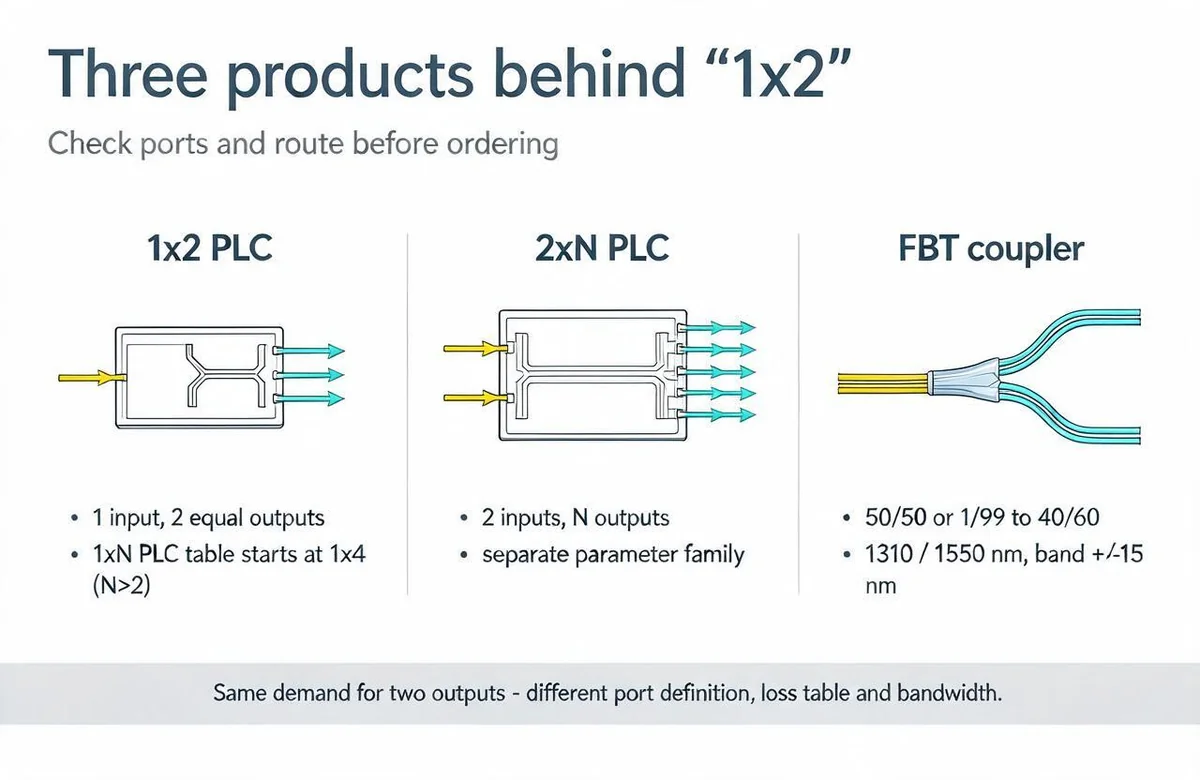
Port count is the first filter. A 1×2 device has one port on the input side and two on the output side; the total is three. A 2×N device has two ports on one side and N on the other, so a 2×4 device holds six ports and a 2×8 holds ten. A 2×2 device carries four ports, two on each side, and is used where a link has to be split and recombined or where both directions of a duplex pair run through one component. Each of these needs its own insertion-loss figure, because the power is divided among a different number of paths.
An FBT coupler is the one family in our catalogue whose two-output specification is openly published. It is built by bundling fibres, fusing and stretching them on a tapering machine while the splitting ratio is monitored, then cutting away the unused fibres so a single fibre remains as the input end. The result can be a near-equal split or a very uneven one, and the same production method covers the whole ratio range.
That leaves the naming problem with the buyer. If the requisition says "1x2", ask the designer which of these three was intended, and ask whether a second input port is present. A wrong answer here changes both the loss budget and the cabinet hardware, so it is cheaper to settle in the enquiry than after the cartons arrive.
Why the 1×N PLC table starts at 1×4
Our 1×N PLC parameter tables are headed "1×N (N > 2)" and list columns for 1×4, 1×8, 1×16, 1×32 and 1×64. Maximum insertion loss, connectors included and measured at 1310/1550 nm, is 7.4 dB, 10.5 dB, 13.8 dB, 17.1 dB and 20.4 dB respectively. Splitting uniformity is 0.7 dB, 0.8 dB, 1.0 dB, 1.5 dB and 2.0 dB, tested at 1310, 1490 and 1550 nm, with 0.5 dB added to the uniformity limit for the 1260–1300 nm and 1600–1650 nm edges. Polarisation dependent loss is 0.2 dB up to 1×8 and 0.3 dB from 1×16 upward. Return loss is at least 45 dB with PC, 50 dB with UPC and 55 dB with APC terminations, directivity is at least 55 dB, and the operating bandwidth is 1260–1650 nm.
The header states the boundary, and the columns confirm it: the table does not publish a 1×2 row. The smallest listed ratio is four outputs, and the loss figures belong to the four- and eight-way columns. A two-way split is easier to fabricate than a four-way split, but the actual figure for a 1×2 PLC part depends on that part's own design — waveguide layout, connector choice, test set-up, and the grade the factory applies. Reading 7.4 dB off the 1×4 column and quietly subtracting a tolerance is not a measurement, it is a guess with a decimal point. Any 1×2 PLC insertion loss, uniformity or PDL figure should come from the supplier's datasheet for the exact part number, quoted with the same test conditions the 1×N table uses.
The same table is repeated across the plug-in, subrack, tray, miniature steel-tube and box-type pages, so this is a consistent statement about the catalogue rather than an omission from one page. A buyer who needs a low port count and wants a PLC part should treat the 1×2 PLC quotation as a part-specific enquiry, not a catalogue lookup. Our guide to splitter technical indicators explains how insertion loss, uniformity and return loss behave in a link, which is useful when you have two candidate figures to compare.
2×N is its own series
The 2×N tables sit directly beneath the 1×N tables and share the same layout: same bandwidth, same PDL progression, same return-loss limits, same uniformity limits, same directivity. Their insertion-loss figures do not match. A 2×4 is rated at 7.7 dB against 7.4 dB for 1×4, 2×8 at 10.8 dB against 10.5 dB, 2×16 at 14.1 dB against 13.8 dB, 2×32 at 17.4 dB against 17.1 dB, and 2×64 at 20.6 dB against 20.4 dB. Every 2×N column is slightly higher than its 1×N counterpart, which reflects the additional input path that the power budget has to carry.
These columns are not interchangeable, and the gap is large enough to matter when it is multiplied across a link. A design that calls for two feeders into one distribution point is a 2×N design, and its path loss should be taken from the 2×N column of the model actually quoted. A design that needs one feeder split into two drop directions is not. Speaking of "1×2 versus 2×N" as if they were two linguistic forms of the same device is the source of a great many mismatched bills of material.
For the budget arithmetic, our PLC splitter loss budget reference lists both families side by side by split ratio so that each column keeps its own values.
| Family | Ports | Published ratio columns | Maximum insertion loss | Operating bandwidth | Loss and PDL character |
|---|---|---|---|---|---|
| 1×N PLC | 1 input, N>2 outputs | 1×4, 1×8, 1×16, 1×32, 1×64 | 7.4 / 10.5 / 13.8 / 17.1 / 20.4 dB, connectors included at 1310/1550 nm | 1260–1650 nm | PDL 0.2–0.3 dB; directivity ≥55 dB; return loss 45/50/55 dB by PC/UPC/APC |
| 2×N PLC | 2 inputs, N>2 outputs | 2×4, 2×8, 2×16, 2×32, 2×64 | 7.7 / 10.8 / 14.1 / 17.4 / 20.6 dB, connectors included at 1310/1550 nm | 1260–1650 nm | PDL 0.2–0.3 dB; directivity ≥55 dB; return loss 45/50/55 dB by PC/UPC/APC |
| FBT, grade P | 1 input, 2 outputs | 50/50, 40/60, 30/70, 20/80, 10/90, 5/95, 2/98, 1/99 | 50/50 ≤3.4 dB; uneven ratios quoted as two values, e.g. 10/90 ≤11.0/0.65 dB | ±15 nm around 1310/1550 nm or another stated wavelength | Typical added loss ≤0.10 dB; PDL ≤0.10 dB; directivity ≥55 dB |
| FBT, grade A | 1 input, 2 outputs | Same ratio list | 50/50 ≤3.6 dB; 10/90 ≤11.5/0.8 dB | ±15 nm around the stated wavelength | Typical added loss ≤0.15 dB; PDL ≤0.15 dB; directivity ≥55 dB |
| 1×2 PLC | 1 input, 2 outputs | Not listed in our 1×N tables | Part-specific; request grade and test conditions | Not stated for a 1×2 row | Part-specific; do not infer from a 1×4 column |
The FBT route for two outputs
For a two-output split, the FBT series is the only family in our catalogue that publishes a complete two-output specification. Grade P gives 50/50 at ≤3.4 dB and grade A at ≤3.6 dB, and the uneven ratios are quoted as a pair of limits, one for the small tap and one for the large leg: 40/60 at ≤4.4/2.6 dB for grade P, 20/80 at ≤7.6/1.2 dB, 10/90 at ≤11.0/0.65 dB, down to 1/99 at ≤21.5/0.2 dB. Grade A shifts each pair slightly higher — 10/90 to ≤11.5/0.8 dB and 1/99 to ≤22.0/0.3 dB. The paired notation matters: it gives the loss on each leg instead of a single lump, which is exactly what a monitoring-tap question needs.
Typical added loss is ≤0.10 dB at grade P and ≤0.15 dB at grade A, PDL ≤0.10 dB and ≤0.15 dB, directivity ≥55 dB, and the operating temperature range is −20 to +70 °C. The operating wavelength is listed as 1310 nm, 1550 nm or others, with a bandwidth of ±15 nm. That narrow window is the single most consequential line in the table for a modern PON link: a coupler specified at 1310/1550 nm with ±15 nm cover is not the same component as a PLC device whose published operating bandwidth reaches 1260–1650 nm.
Unequal ratios are where FBT earns its place. A 90/10 monitoring tap, written in our table as 10/90, sends a tenth of the light to the monitoring path and keeps the rest on the traffic fibre. If the design intent is "a small tap for a power monitor", asking for a 50/50 coupler and attenuating one leg wastes signal and money. Both ends of the ratio list exist for that purpose, from 1/99 up to 40/60, and they are specified as different part numbers.
Bandwidth, added loss and PDL: what the two routes state
The two families describe their optical behaviour in different terms, and comparing them requires converting those statements into something like-for-like. PLC tables state a maximum insertion loss per split ratio over a 1260–1650 nm operating bandwidth, tested at 1310/1550 nm with connectors included. FBT tables state a maximum insertion loss per ratio, a typical additional loss, a PDL ceiling and a wavelength window of ±15 nm. The PLC figure is a worst-case number across a wide band with connectors in the path; the FBT figure is a limit at the stated wavelength, and the page does not say whether connectors are included. If connector loss matters in a tight budget, that question goes to the supplier before the order, not after.
PDL follows the same pattern. PLC parts carry 0.2 dB up to 1×8 and 0.3 dB from 1×16 upward. FBT parts carry 0.10 dB at grade P and 0.15 dB at grade A. A designer working with polarisation-sensitive receivers will notice the difference; a plain GPON drop will not. The FBT grade choice is therefore a small, cheap lever for a tighter polarisation budget, while the PLC split suits wideband distribution where an extra 0.2–0.3 dB of PDL is unremarkable.
Bandwidth is the dividing line with the most practical weight. A link that carries 1490 nm downstream, 1310 nm upstream and a 1550 nm monitoring or video channel sits inside the PLC 1260–1650 nm band by definition. An FBT coupler at 1310/1550 nm with ±15 nm does not claim coverage at 1490 nm; if your wavelength plan includes that channel, the coupler must be specified for it explicitly, or the design should use a PLC part. This is not a quality ranking — it is a statement of where each device's published window applies.
Our loss-budget reference carries the same definitions, so a figure taken from this article can be traced back to the same source conditions when it reaches a design review.
Packages and cabinets: the part that does not travel alone
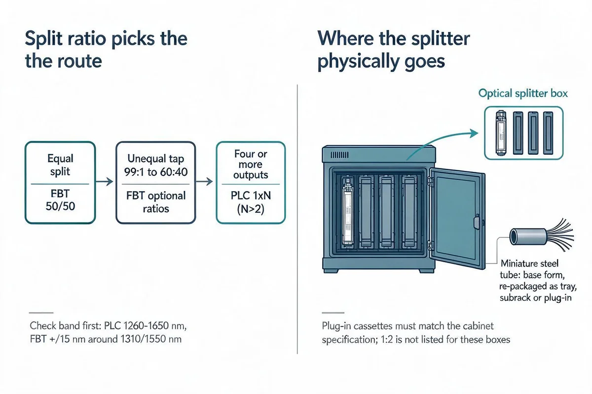
A splitter cartridge without a home is not an order. The miniature steel-tube package is the base form in our range: it can be used directly inside an optical network terminal box, or re-packaged as a tray, subrack or plug-in module. The plug-in form is defined by telecom operator specifications and installs in distribution cabinets or boxes that meet the corresponding specification, such as jump-free optical cross-connect cabinets. Different splitting ratios can be combined, and SC or LC connectors can be customised, but "combined" and "customised" are options on an order, not automatic features of the cabinet.
A splitter box accepts plug-in cartridges in the ratios it lists. The 32-core SMC box HJ-GFS-KCW-32C reserves four plug-in slots and lists 1:4, 1:8, 1:16 and 1:32 as optional cartridges. The 16-core plastic box HJ-GFS-KSW-16C reserves two slots and lists 1:4, 1:8 and 1:16. Each model's list is the boundary for that model; extending one box's option list to a smaller box is how specifications get lost between quotation and delivery.
The 1:2 gap in the enclosure line
The four-slot SMC box and the smaller plastic boxes do not list a 1:2 cartridge, and no other splitter box in the catalogue shows one either. A designer who needs a two-way split at the cabinet has two practical options, and both are decisions to confirm rather than features to assume. The first is a cartridge of the 1:2 type built to the operator's own specification, which exists only if the factory confirms the part during quotation. The second is to mount an FBT coupler inside the enclosure or a terminal box, which means checking that the coupler's package, pigtail length and connector type suit the box's internal space and adapter arrangement.
Neither option should be written into a bill of materials as "included in the splitter box". The box pages describe the boxes and their optional cartridges; a 1:2 cartridge is a request line on an enquiry, and the answer decides whether that configuration ships. Stating this plainly at quotation costs one question. Discovering it at commissioning costs a re-order. The PLC splitter package selection guide covers the mechanical side of that choice in more detail.
Order of decisions: ratio, then band, then loss, then enclosure
Start with the split ratio because it selects the family. An equal split of two outputs can be served by an FBT 50/50 at either grade. An unequal tap for monitoring sits in the FBT ratio list from 1/99 to 40/60, with the leg values read from the grade column you intend to buy. Any requirement for three or more outputs leaves the two-output families altogether and enters the 1×N PLC columns, which begin at 1×4. A two-input, many-output plan enters 2×N, with its own loss column.
Then check the wavelength. If every channel in the link lives inside a ±15 nm window around 1310 or 1550 nm, FBT is viable. If the design carries 1490 nm or needs one part to work across 1260–1650 nm, the PLC bandwidth statement is the one that fits, and the two-output question becomes a part-specific 1×2 PLC request rather than a catalogue pick.
Only then compare loss classes. For FBT, the gap between grade P and grade A is 0.2 dB at 50/50 and grows slightly at uneven ratios, with PDL moving from 0.10 to 0.15 dB; that is a straightforward trade to price. For PLC, the comparison is between whatever the supplier's 1×2 datasheet states and the 1×N column you would otherwise have used — and those should not be assumed to move in a predictable direction unless the datasheet says so.
Enclosure comes last, because it is the constraint that cannot be negotiated upwards. A plug-in cartridge has to match the cabinet specification and the box's slot count. A steel-tube device has to fit the space and the pigtail routing. A 1:2 cartridge has to be confirmed as an orderable part before it can be planned into a slot.
A confirmation list you can send to any supplier
The fields below can be copied into an enquiry as they stand. Each one closes a decision that a vague datasheet leaves open, and a supplier who answers all of them has given you a specification you can compare with another quotation.
| Field | What to ask, precisely | Why it changes the order |
|---|---|---|
| Split ratio and port definition | State 1×2, 2×2 or 2×N, with the number of ports on the input and output side; for an uneven ratio, give both legs, e.g. 10/90. | A 2×4 is not a 1×2 with extra outputs; the price, footprint and loss figure differ. |
| Technology route | PLC (planar waveguide) or FBT (fused taper). | Determines which parameter table applies and whether a 1260–1650 nm statement is available. |
| Insertion loss value type | Is the figure a typical value or a maximum? Which grade — P or A, or an equivalent PLC grade? | A typical number in a budget becomes a maximum at the worst-case review, and the shortfall has to be carried somewhere. |
| Connector inclusion | Does the stated loss include the connectors, and at how many interfaces? | One dB of connector loss can decide whether a design passes its margin. |
| Test wavelength | At which wavelengths was the loss measured: 1310, 1550, 1490, or a sweep? | Values at 1310/1550 nm do not automatically describe 1490 nm behaviour. |
| Uniformity and band-edge correction | What is the uniformity limit, and does it carry the +0.5 dB correction for 1260–1300 nm and 1600–1650 nm? | Uniformity limits quoted without the edge correction understate worst-case spread. |
| PDL | Maximum polarisation dependent loss for this ratio and grade. | Matters for polarisation-sensitive receivers; the two routes publish different ceilings. |
| Directivity | Minimum directivity, normally ≥55 dB for both families. | Confirms the part isolates the output legs from backward reflections in the stated condition. |
| Return loss by connector polish | Minimum return loss for PC, UPC and APC terminations separately. | 45, 50 and 55 dB are different limits; a single number hides which polish it belongs to. |
| Operating bandwidth | The stated band in nm, for this family. PLC states 1260–1650 nm; FBT states ±15 nm around 1310/1550 nm or another wavelength. | Decides whether the part covers the full channel plan of the link. |
| Package and enclosure type | Plug-in, tray, subrack, box or steel tube; if plug-in, the cabinet or box model it must fit. | A cartridge that does not match the cabinet specification cannot be installed. |
| Connectors and customisation | SC or LC, polish type, pigtail length and whether those are standard or custom. | Custom options change the part number and the delivery schedule. |
What a supplier should confirm in writing
Two items on that list cannot be answered from our current catalogue: the loss specification of a 1×2 PLC part, and the availability of a 1:2 plug-in cartridge for a splitter box. Both are genuine order lines that a factory can confirm, and both are worth having in writing before a purchase order is raised, because neither can be read off a published table.
The rest of the list has published answers. Our PLC 1×N and 2×N tables, the plug-in specification page and the FBT series table give the ratio columns, loss ceilings, PDL, directivity, return loss and bandwidth with their test conditions. Send those values to the supplier as the specification you expect, and ask for any deviation in writing. A quotation that quietly substitutes a typical value for a maximum, or drops the +0.5 dB band-edge correction, is not the same product even when the part number looks similar.
For a two-output requirement, the most efficient first move is to decide equal or unequal, then send the confirmation table with the ratio, the band and the intended enclosure already filled in. One round of that request usually settles the specification. The FBT series specification page and the plug-in series specification page can be attached to the enquiry, and the optical splitter box page covers slot count and cartridge options if the split is going inside an enclosure.
If a two-output split turns out to be part of a larger distribution plan, the 1×N and 2×N figures above shape the rest of the budget; if it is a single tap for monitoring, the FBT ratio list is where the answer lives. Either way, the part number should describe the product, not the buyer's shorthand.
——END——