

At a dirty connector, insertion loss and return loss can move in opposite directions — and one of them can stay comfortably inside its budget while the other collapses far below what the link needs. That asymmetry is what makes end-face contamination so hard to argue about on site. A technician asks for three things: a lint-free dry clean, an inspection at magnification, and only then a decision about whether to reintroduce solvent. Everything else in this routine follows from how particles, oil, and scratches behave differently at the mating plane.
What contamination does to insertion loss and return loss
Particles and oils do not behave alike at a mating plane, and that difference decides how a link fails. The clearest public evidence comes from a multi-company programme run through the National Electronics Manufacturing Initiative, which applied scratches, particles and fingerprint oil to SC connectors and measured insertion loss and return loss at 1310 nm and 1550 nm.1
Particles that land on the core are the catastrophic case. With clean connectors the programme recorded insertion loss of 0.23 dB and 0.20 dB at 1550 nm and 1310 nm; with particles on the core the same measurements read 21.9 dB and 22.8 dB, while return loss dropped from roughly 53 dB to 20 dB.2 A smaller blocked-core case still moved insertion loss from 0.39 dB and 0.51 dB to 2.88 dB and 3.61 dB, and return loss from 56.2 dB and 54.6 dB to 37.1 dB and 34.5 dB.3 Either result is several times what the single-mode connector table for this product family allows after the routine tests, which is 0.5 dB insertion loss and a return-loss variation of 5 dB at 1310 nm and 1550 nm.4
Oil from a fingerprint behaves differently, which explains why return-loss complaints often arrive with no matching insertion-loss complaint. The programme's conclusion states that oil contamination caused significant return-loss degradation of 10–12 dB and no significant change in insertion loss.5 An end face can pass a loss test and still fail the specification the network was designed around, because a film a few nanometres thick reflects light back toward the source without blocking much forward light.
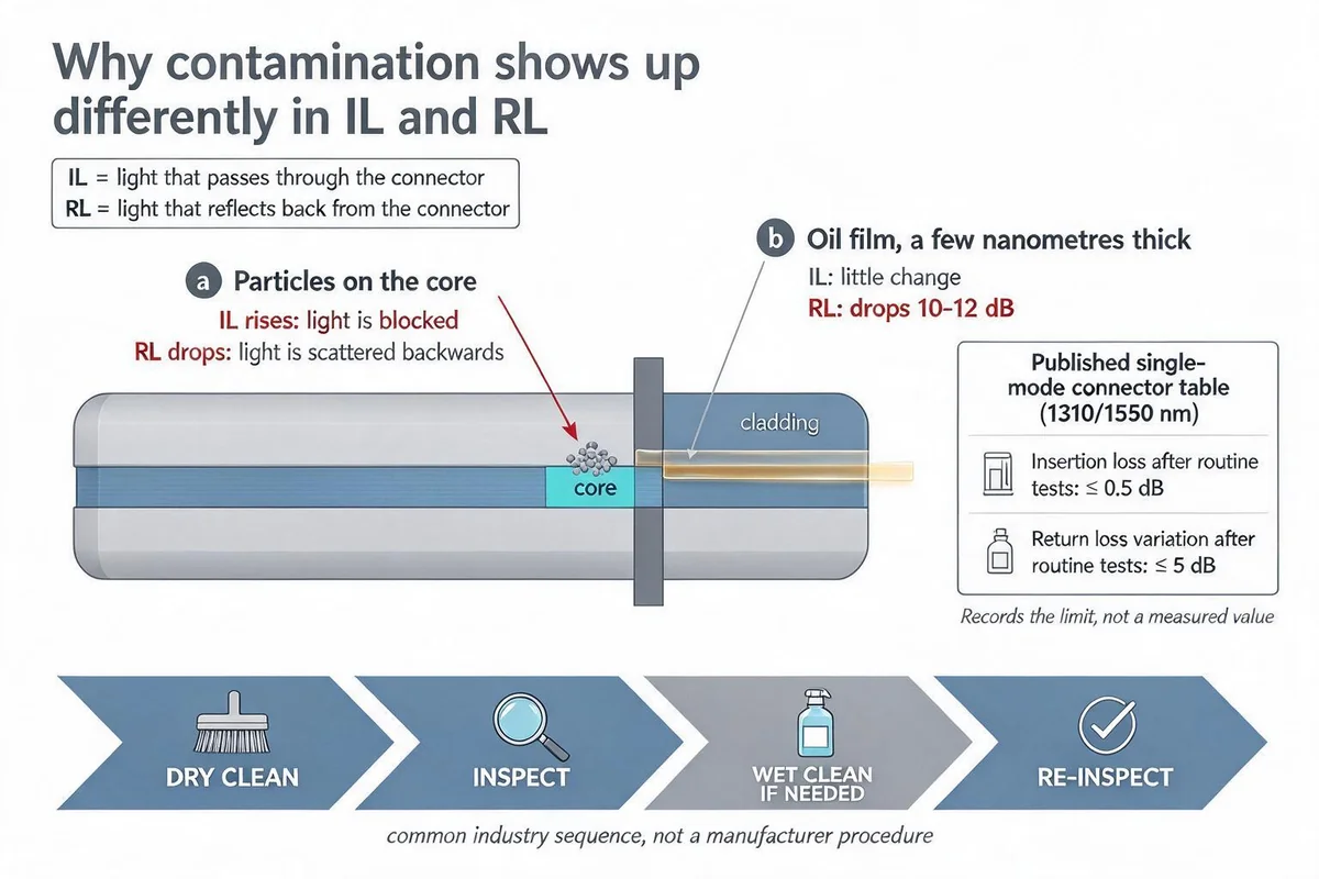
Scratches sit between the two extremes and deserve separating from dirt, because they cannot be cleaned off. In the same programme, scratches of about 2 µm or less within the mode field diameter had no impact on insertion loss but could degrade return loss, and how far it fell depended on the width, depth and number of scratches crossing the mode field; polishing marks outside the mode field affected neither measurement.6 If a re-inspection after cleaning still shows a return-loss problem with no visible contamination, the end face is damaged rather than dirty, and further cleaning passes will not help.
Why clean a connector that already passes
The reason is that a dirty end face biases the measurement in its favour. A lifted reflection behaves like a small optical return at the connector, adding loss to the link while the connector is dirty and removing that loss once it is cleaned. One test-equipment vendor quantified the effect as a link-loss allowance of 1.39 dB on a typical link: a dirty connector can absorb enough loss to hold a link inside its budget, and cleaning it then pushes the link outside.7 That figure is the vendor's own allowance for a typical link, not a standard and not a value to apply to every cable.
For a construction or O&M team the consequence is direct: acceptance data is only trustworthy if the end faces were clean when the measurement was taken. Recording a link as passing while its connectors are dirty hands the next crew a link that will drift outside budget after the first proper clean, usually during a fault call rather than during commissioning.
A four-step field routine: dry, inspect, wet only if needed, re-inspect
The order below is the sequence generally used in outside-plant and data-centre practice, not a procedure written by this manufacturer. It works because it removes the cheapest and most likely cause first, and because inspection rather than the cleaning action decides whether the connector is acceptable.
Dry clean the end face first. A dry wipe or dry stroke removes loose dust and most of the particle load without leaving solvent residue behind. It is the standard starting point for the same reason a wet pass is not: whatever is applied has to be removed again before the end face can be judged.
Inspect before deciding anything else. Look at the cleaned end face at magnification and check the core and the area around it. Skipping this step is the usual reason a link is mated twice and fails twice, because without looking nobody can tell whether the face is clean, oily or scratched, and those three conditions need different responses.
Wet clean only when a residue remains. If inspection still shows an oil film, a smear or a stubborn mark after a dry pass, use a solvent suitable for the connector and follow the cleaner manufacturer's instructions. Wet cleaning is the answer to a residue dry cleaning did not remove, not a routine second step, and it must be followed by drying and another inspection.
Re-inspect, then re-test the link. The end face returns to the accepted condition before the connector is mated, and the link measurement is repeated afterwards. A clean end face followed by an unchanged loss or return-loss figure means the contamination was not the whole problem.
One risk sits inside the cleaning action. The same programme reported that cleaning fibre-optic connectors can produce an electrostatic charge effect during the process, and tested air ionizers and dust caps as countermeasures.8 A charged end face attracts the particles that were just removed, so a connector left open on a dusty pole between cleaning and mating can re-contaminate itself. Keep the dust cap on until the moment of mating.
The programme also recorded that, at the time of that work, there was no industry-wide standard for connector cleanliness, and that inspecting and cleaning contaminated connectors affected manufacturing time and therefore test and product cost in high-density port systems.9 Field practice varies by contract and customer specification, so the sequence above is a sound default rather than a substitute for the acceptance criteria a project actually names.
Match the cleaning rod to the ferrule, not to the pen
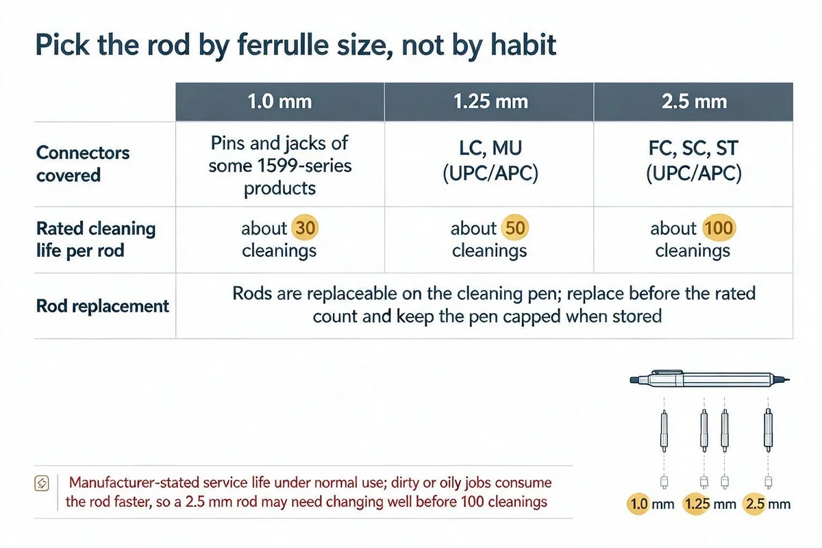
Ferrule diameter decides which rod goes on the pen, and getting it wrong wastes time or damages the end face. The electric end-face cleaning pen used in this product line takes three rod sizes, each covering a defined set of interfaces.
- 2.5 mm: FC, SC and ST connectors in UPC and APC, the traditional outside-plant interfaces.
- 1.25 mm: LC and MU connectors in UPC and APC, the small-form-factor interfaces found on OLT ports, ONTs and high-density patch panels.
- 1.0 mm: pins and jacks of some 1599-series products, not a general-purpose size for every small connector.
These coverage statements are the boundary the pen can be relied on within.10 A 2.5 mm rod is right for an SC drop terminal and wrong for an LC port on an ONT: forcing the larger rod into a smaller adapter presses the tip against the ferrule edge instead of wiping across it. A 1.0 mm rod on a 1599-series part is correct only for the pins and jacks listed, so confirm the interface before assuming the smallest rod covers it.
The pen removes anhydrous stains and, according to the manufacturer, its high rotation speed produces an effect similar to end-face polishing, which is why it is presented as suitable for stubborn stains on connectors that have not been cleaned for a long time.11 That is also why the end face gets inspected afterwards rather than cleaned repeatedly on the assumption that more passes must be better.
Rated rod life is a planning number, not a guarantee
The published service life is about 30 cleanings for the 1.0 mm rod, about 50 for the 1.25 mm rod and about 100 for the 2.5 mm rod, and the rods are replaceable.12 Those are counts the manufacturer states the rods can reach, not a promise that a particular rod still cleans well at the last one: a soiled rod carries its previous contamination, and a worn rod stops removing what is on the ferrule.
Planning from the numbers is straightforward. A crew working mostly on LC patch panels uses 1.25 mm rods about twice as fast as SC work at the same connector count, because that rod is rated at half the 2.5 mm rod's life. Where contamination is heavy, oily or long overdue, expect to replace rods well before the rated count and treat a spare rod as a vehicle consumable rather than something ordered after a failure.
Storage matters as much as the count. The pen is rated for −10 °C to 40 °C in operation and −20 °C to 40 °C in storage, so it belongs in a bag rather than loose on a seat or in a closed cab that overheats on a summer day or freezes overnight in winter.13
What belongs in the toolkit, and what it cannot do
Cleaning answers one question, and the tools for the others are not interchangeable with it. The maintenance toolkit for this product line combines a handheld light source, a handheld optical power meter, a visual fault locator and a cleaning pen, plus standard test jumpers and adapters matched to the network or link being tested.14
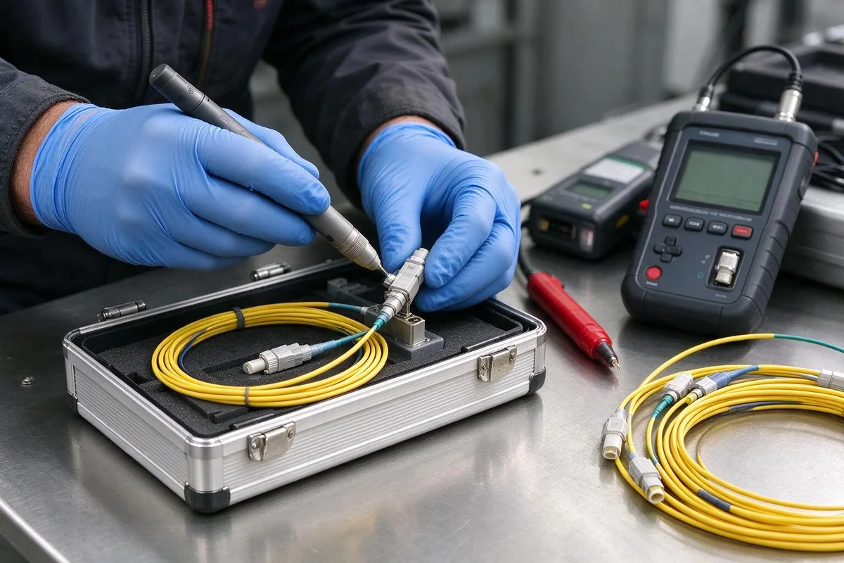
The list is deliberately modest, and its limits matter. The light source and power meter measure link loss, the visual fault locator finds breaks and macro-bends where light escapes, and the cleaning pen removes contamination. None of them inspects an end face at magnification and none measures return loss directly, which is why the inspection step needs its own viewer and why a return-loss complaint cannot be settled by a loss measurement alone.
The matched jumpers and adapters matter more than they look. A reference jumper with a dirty or damaged end face contributes that contamination to every measurement, and a test lead whose connector does not match the port forces an adapter into the path that adds a mating plane nobody counted. Checking the leads' end faces and capping them between uses is part of keeping the numbers honest. The kit is specified for manual link-loss testing and manual cleaning of connector contact end faces, not for automated test or accuracy reporting, and the jumper and adapter types follow the link being worked on.15
What the factory checks, and what that tells a field crew
Two inspection steps in production answer two different questions, and knowing which is which stops a crew expecting the wrong thing from a new connector. During manufacture a high-resolution Integrated End Face Inspection Instrument checks the cleanliness and integrity of connector end faces.16 A 3D interferometer in the same process inspects end-face geometric parameters, meaning the shape of the ferrule tip rather than what is sitting on it.
Cleanliness and geometry are separate questions. A connector that leaves the factory clean and geometrically correct can still be contaminated on site by an uncapped adapter, a dusty patch panel, a fingerprint during handling or a dirty test lead. Factory cleanliness describes the condition at dispatch; it does not remove the need to clean and inspect at the point of mating.
The separation also stops the wrong diagnosis. A brand-new connector that fails return loss with no visible contamination on a properly inspected end face will not be fixed by another cleaning pass; the answer lies in the end-face condition, the mating pair or the adapter.
Recording the clean-and-inspect step
A routine that leaves no trace cannot settle the argument that follows a marginal link. The minimum useful record is short and fits beside the loss measurements a crew already takes.
- The connector position and its interface type, so the rod size used is on record.
- The inspection result before and after cleaning: clean, oily or scratched, per position rather than a single line for the whole link, so a later fault traces to a connector.
- Whether a wet clean was used, and where, since that is the position where a residue problem recurs.
- Link loss and return loss with the wavelength used and a time stamp, measured after the end face passed inspection.
- The rod in service and its accumulated count, so replacement is planned rather than discovered mid-job.
Written this way, cleaning stops being a habit and becomes evidence. When the same drop is called in again, the crew can see whether the face was accepted as clean and what the numbers were, which is the difference between re-cleaning the same connector and looking for the real cause. It is also where a link's measured performance stops depending on how dirty the connectors happened to be on test day, which is the number the acceptance discussion will turn on later.
Four habits that undo the routine
Using the wrong rod size. A 2.5 mm rod on an LC adapter, or a 1.0 mm rod on any connector outside the 1599-series pins and jacks it is specified for, either misses the ferrule face or works at the wrong angle. Confirm the interface before the rod goes on.
Skipping the re-inspection. Cleaning without looking is not verification; the three outcomes lead to three different next steps, and only inspection separates them.
Wet cleaning everything. A solvent pass on every connector leaves residue to dry and can mask a scratch as a smear. Wet cleaning belongs where dry cleaning left something behind.
Testing with a dirty reference lead. A dirty test jumper contaminates the end faces being measured and adds its own loss and reflection to the reading. The leads deserve the same inspection as the link.
Start from the interfaces on the work
The right kit starts from the mix of interfaces on the job, not from a single tool. A crew working mainly on SC drops needs the 2.5 mm rod with room for spares; an O&M team working on LC ports at ONTs and OLTs needs the 1.25 mm rod and should plan for roughly double the replacement rate. Both need the light source, power meter and visual fault locator to check the link before and after cleaning, and matched jumpers and adapters so the measurement path matches the ports under test.
If you are specifying or restocking field kits and want the rod sizes, jumper types and adapters confirmed against the interfaces in your own network, send the interface list and the ports you test, and the configuration can be matched to it.
——END——