

Two 100G link designs can carry identical connector part numbers and still end up with different measured loss, because the number printed beside a connector is not the number a link experiences. On a parallel MPO link the loss of eight fibers is decided by the worst lane, and each mated connection sits in that lane's path. On a single-mode link the same catalogue page can offer 0.35 dB before conditioning and 0.5 dB after, an APC grade at 60 dB return loss and a UPC grade at 50 dB. Reading both tables the same way is where purchasing mistakes start. The optical fiber connector range publishes both families, and the two tables are built on different bases.
What a connector rating actually describes
A connector is the hardware at the end of a fiber. Once two connectors are mated through an adapter, the loss belongs to the connection, not to either connector alone. The Fiber Optic Association makes the distinction bluntly in its guidance on calculating loss budgets: “Connectors have no loss; only connections have loss.” A vendor's dB figure is therefore a measured property of a mated pair against a reference connector, not a property you can add up per part number on a purchase order.
That matters more for MPO than for single-fiber parts. An MPO is a multi-core connector, so a 12-fiber trunk has, in principle, twelve independent paths sharing one housing and one ferrule. A link built from it uses fewer than twelve, and the loss that matters is the sum along the fibers the transceiver actually uses, with every patch, module and adapter in that path counted once per mating.
The MPO table has six columns, not four values
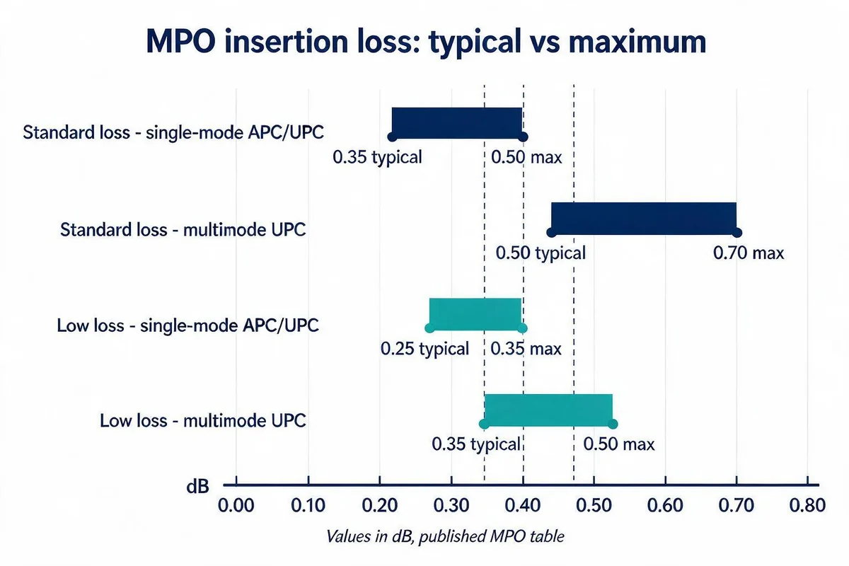
Our MPO specification is organised by two independent axes: loss grade (standard or low loss) and fiber type with its end face. Single-mode appears twice, once as APC and once as UPC, in each grade; multimode appears once per grade as UPC, because the published multimode columns carry no APC variant. Reading across rows instead of down a column is the most common way a buyer picks the wrong cell.
| Grade | Fiber and end face | Insertion loss, typical | Insertion loss, maximum | Return loss |
|---|---|---|---|---|
| Standard loss | Single-mode APC | 0.35 dB | 0.5 dB | 60 dB |
| Standard loss | Single-mode UPC | 0.35 dB | 0.5 dB | 50 dB |
| Low loss | Single-mode APC | 0.25 dB | 0.35 dB | 60 dB |
| Low loss | Single-mode UPC | 0.25 dB | 0.35 dB | 50 dB |
| Standard loss | Multimode UPC | 0.5 dB | 0.7 dB | 20 dB |
| Low loss | Multimode UPC | 0.35 dB | 0.5 dB | 20 dB |
The gap between typical and maximum is the part buyers under-use. Along the measured lot, the typical figure sits well below the maximum in the same column. A low-loss maximum of 0.35 dB is also the standard-loss typical value, so a quotation described only as “0.35 dB MPO” is compatible with two different products. A quotation is unambiguous only when the grade label and the word maximum appear next to the number.
Return loss is recorded as a single figure per end-face type rather than as a typical/maximum pair, because it is a minimum acceptance value. For single-mode APC it is 60 dB and for single-mode UPC 50 dB. Both multimode grades carry 20 dB, which is the published expectation for multimode reflectance rather than a weaker single-mode part. Ten decibels of separation between APC and UPC is a different class of reflectance, not a rounding difference.
Why the single-mode table changes when tests are added
The single-mode connector series publishes two rows that look like a contradiction until the test column is read. Before any test, at 1310 nm and 1550 nm, insertion loss is ≤0.35 dB for both PC/UPC and APC types, with return loss ≥45 dB for PC, ≥50 dB for UPC and ≥60 dB for APC. After interchangeability, mechanical durability, tensile, high and low temperature, damp heat, salt spray and transportation tests, insertion loss becomes ≤0.5 dB, and return loss ≥43 dB, ≥48 dB and ≥58 dB respectively.
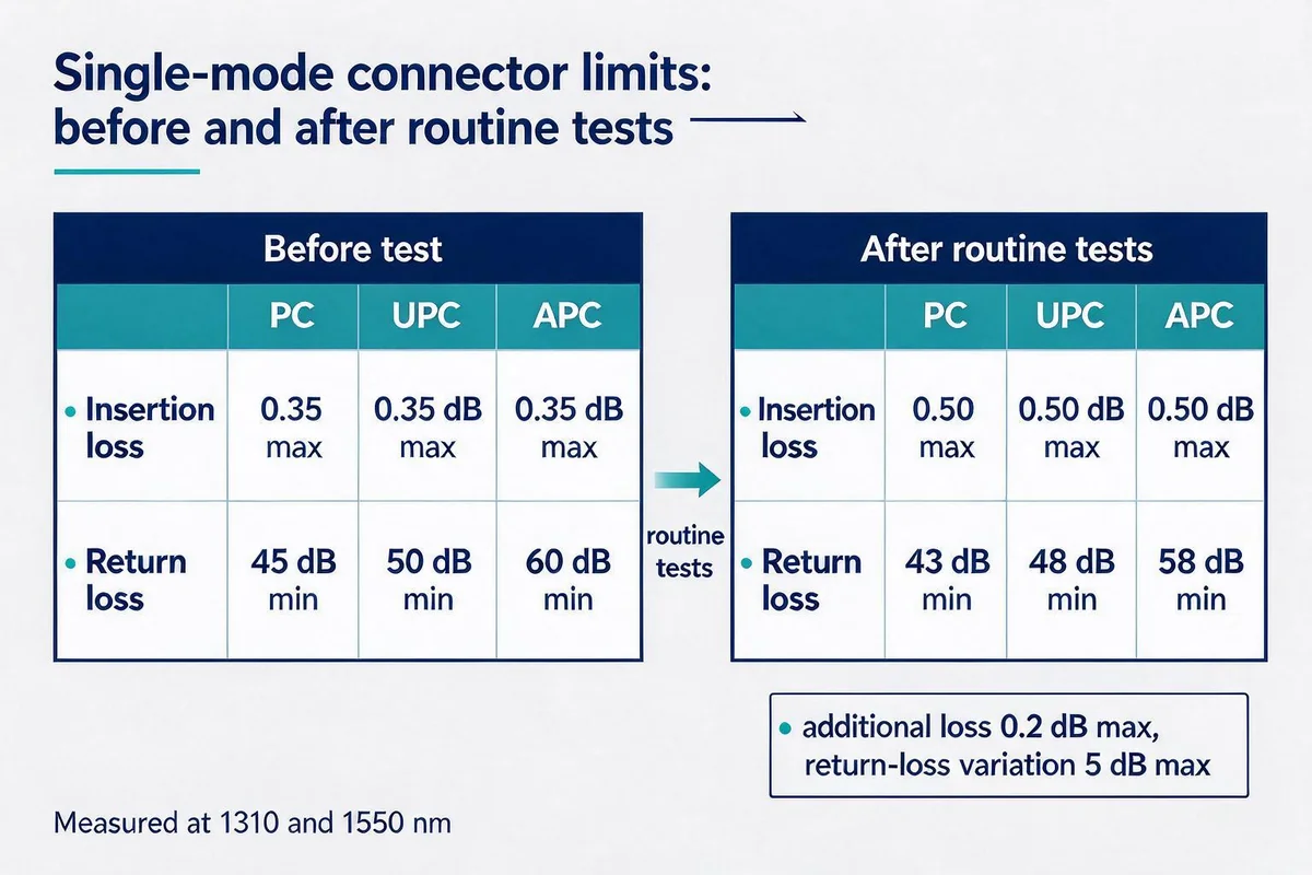
Nothing in the second row retracts the first. The conditioned table carries two change limits that define how the numbers relate: additional loss of ≤0.2 dB, and return-loss variation of ≤5 dB. Additional loss is the post-test insertion loss minus the pre-test figure, counted as zero if the difference is negative; return-loss variation is the pre-test value minus the post-test value, again floored at zero. Both rows therefore hold at once, and the 0.5 dB figure describes a connector that has already been through the test sequence rather than a fresh one.
That is the useful question for a data-centre buyer: which row does the acceptance test match? A factory test performed at shipment is closest to the pre-test row. A site acceptance test after a trunk has been installed, re-patched and moved sits closer to the conditioned row, because the connector has already been cycled and exposed. Quoting 0.35 dB as the acceptance criterion for a link that has been handled will fail parts that meet the after-test limit, and quoting 0.5 dB for incoming inspection will accept parts that do not meet the pre-test limit.
One separate question sits outside the two rows above: whether a single-mode port is a factory splice-on or a field termination. FOA answers it with 0.1–0.2 dB for factory-made fusion-spliced single-mode connectors and up to 0.5–1.0 dB, with unacceptable reflectance, for field-terminated single-mode connectors, which FOA does not recommend. Those figures describe single-fiber terminations, not a grade of our connector series, and they have no reading against the pre-test and post-test rows above, which are the values to quote for this series.
Mechanical and environmental limits are the envelope, not a performance tier
Five values sit outside the two optical tables and describe what the connector survives, not how well it couples light: interchangeability ≤0.3 dB, durability ≤0.2 dB, tensile strength ≥50 N, an operating temperature range of −20 to +60 °C, and operating humidity of 5–95 per cent non-condensing.
Interchangeability and durability sit next to the loss grades because both describe change after handling rather than loss at manufacture. A mated pair that shifts by up to 0.3 dB when re-mated can use up the 0.35 dB a low-loss grade gained over a standard-loss part, and durability at ≤0.2 dB sets the change allowed across repeated matings for the specified condition. Operating temperature and humidity belong to the deployment: the 5–95 per cent range is qualified non-condensing, so a route where condensation occurs falls outside this envelope.
A port count becomes a per-link ceiling
The arithmetic that turns these figures into a budget is a sum, and the count of terms follows from how many fibers a transceiver drives and how long each path is. A 40G or 100G short-reach link built on parallel optics uses several fibers of one trunk, so the mated connections on the fibers in use add up, and any patch panel, adapter or module in the route adds more. The example below takes four mated connections per direction as its only figure; the fiber count and the number of patch points depend on the transceiver, the polarity plan and the physical route.
If a link uses four mated connections per direction, single-mode low-loss MPO at its 0.35 dB maximum gives 1.4 dB, and multimode standard-loss MPO at its 0.7 dB maximum gives 2.8 dB. Each figure counts only those four mated connections and does not include any patch, module or adapter connection outside them, so it is not the acceptance ceiling of a specific transceiver configuration; add every further mating on the lane to reach a link figure. When the transceiver and polarity plan do not yet fix the connection count, carry the count from the quotation list below rather than the example. The comparison shows what the grade choice does to a fixed connection count, and why the multimode low-loss grade at 0.5 dB maximum sits between them.
Those sums are built from maximum values, and a maximum leaves nothing for the field. The FOA notes that, as a general rule, link loss margin should be greater than about 3 dB to allow for degradation over time, and adds that the rule is irrelevant when the power budget itself is near 2 dB. A link planned at exactly the passive sum therefore has no room for a degraded patch. A budget built from typical values will look comfortable and tell you nothing about a worst-case lot.
Return loss separates the two families more sharply than insertion loss
Insertion loss separates the grades by 0.1–0.2 dB at the same fiber type, but return loss separates fiber types by tens of decibels. For a link whose performance depends on reflected light staying out of the transmitter, the end-face decision moves the figure further than the grade decision does.
That is why a multimode 20 dB figure cannot be placed in the same column as a single-mode APC grade and read as a fixed number of decibels worse. The two values describe different fibre geometries and different reflectance behaviour, and the multimode figure is the published expectation for that fibre type. Where a design needs high return loss, the choice is single-mode APC, not a low-loss multimode part.
Our indoor and OM3/OM4 single-fiber multimode series carry their own insertion-loss clauses in their own tables; those clauses are not a basis for accepting an MPO, and the MPO grade columns above are the values that govern an MPO order.
The FOA observes that the EIA/TIA-568 allowance of 0.75 dB maximum per connector is generally much too high except for array connectors such as MPO, which is why the MPO grade columns and not a general connector allowance belong in the BOM.
APC and UPC cannot be mixed on single-mode MPO
The two single-mode columns are not two options within one product; they are two product families with different ferrule geometry. An APC end face is angled and a UPC end face is flat, so mating them across a single-mode MPO array puts a wedge gap between the fibers at the interface. The consequences are an increase in insertion loss at every fiber that meets the gap, reflectance well outside either published figure, and a physical contact that neither column describes. The rule for the buyer is short: one polish type end to end, including the adapter and the array's key orientation, and that polish type written on the purchase order rather than inferred from the fibre type.
The table on this page lists single-mode APC and UPC columns, a multimode UPC column and no multimode APC column. Any multimode APC requirement therefore needs written confirmation or a custom enquiry and must not be read from the table's silence. Single-mode appears as both end faces, so the polish type has to be selected rather than defaulted. Checking the end-face field before the grade field settles that question first.
What to send with a quotation request
Four fields decide whether a quotation matches the budget you drew, and none of them is the price. Send the fiber count and the number of ports it serves; a 12-fiber trunk for an eight-fiber link leaves four fibers unused, and the lane count drives the connection count in the sum. Send the fiber type and end face as a pair, single-mode APC, single-mode UPC or multimode UPC, and state that the polish type must not be substituted. Send the loss grade as standard or low loss, and say whether the budget uses the typical or the maximum figure.
Polarity belongs in the same message. MPO links need a defined mapping from position to position, and our production process lists an MPO insertion, return-loss and polarity test before shipment, so the polarity method can be stated on the order rather than resolved on site. Confirm the acceptance test method with the supplier in writing before the order, on the same reference basis as the loss budget. Alongside it, name the reference method used for the acceptance test. A one-cable reference includes both end connectors in the measured value, while the three-cable reference used for plug-and-jack connectors such as MPO excludes the end connectors, so an identical cable plant can pass under one method and fail under the other. Whatever method is agreed, the loss budget has to be calculated on the same basis.
The MPO Series Fiber Optic Connectors page carries the full specification table behind this article, and the Indoor Flexible Fiber Series Connectors page carries the single-mode before-and-after-test rows. Where a limit matters to the acceptance test, the benchtop insertion and return-loss tester states its own accuracy, ±0.25 dB for insertion loss and ±0.5 dB for return loss, and that accuracy belongs in the test plan rather than in the margin. Its insertion-loss channel covers 850, 1300, 1310 and 1550 nm while return loss is offered at 1310 and 1550 nm, so a multimode insertion-loss check has a test path even though the return-loss figure does not. Build the request on those fields and that reference method; the sales team can confirm grade, end face, polarity and test method against it before the order is placed.
——END——