

Splitter packages reach a procurement desk under four or five different product names, often from the same supplier, and the order they are presented in makes them look interchangeable. A plug-in cassette bought for a tray-only distribution frame has nowhere to mount, and a 19-inch subrack ordered for a pole-mounted box has nowhere to sit. What decides whether the project fits is the mounting interface inside the enclosure, and on most live projects it is already fixed by the time the splitter is ordered.
The five optical splitter series share the same device tier. A PLC splitter is an integrated waveguide power-splitter on a quartz substrate, and in the miniature steel tube format it is the primary package of the splitter. That primary package is then re-packaged as a subrack, plug-in or tray unit, or used directly inside an optical network termination box. Box, tray, plug-in and subrack are mounting solutions built around one device, so they can be compared on enclosure fit rather than on optical performance.
Five PLC splitter package forms and where each one mounts
| Form | Where it mounts | Enclosure shape it needs | Capacity and interface notes |
|---|---|---|---|
| Miniature steel tube | Inside an optical network termination box, or re-packaged into another form | No mounting hardware of its own | Primary package of the PLC device; the base for the other series |
| Plug-in | Slot in a distribution cabinet or box that meets the operator specification, including jump-free optical cross-connect cabinets | Slim cassette in a defined socket | Ratios freely combined; SC or LC connectors per customer request; the enclosure defines the slot |
| Box | Inside a compatible existing cross-connect cabinet that has interior space | Compact closed unit, smaller than the cabinet cavity | Compact housing; one device can carry more than 32 splitting channels |
| Tray | Standard fiber distribution frames and optical cable cross-connect cabinets | Flat tray on a frame shelf | Designed for high installation density, easy use and easy maintenance |
| Subrack | 19-inch standard rack | 1U rack chassis, 483 x 200 x 43.5 mm | Standard chassis, box-type splitter with connectors and standard flange |
Reading the table from the inside out makes the pattern obvious. The tube is the device. Everything above it exists to attach that device to something already bolted down in the field, and each attachment needs a different socket: a cassette slot, a cabinet interior, a shelf, or a rack unit.
Plug-in splitters: the slot specification comes from the operator
The plug-in form is not a general-purpose cassette. Its dimensions and socket are defined by telecom operator specifications, and it installs in distribution cabinets or boxes that meet those specifications, such as jump-free optical cross-connect cabinets. Two commercial properties follow from that arrangement. Splitting ratios can be freely combined, so one slot standard covers different PON designs, and SC or LC connectors can be customized to the customer's request. The module is compact enough to go into existing cross-connect cabinets without a specially designed, large reserved space.
When the cabinet is already on the operator's bill of quantities, the slot is effectively frozen. Ask for the slot drawing, the adapter plate and the connector interface before the splitter is quoted, because a module that meets the operator's default footprint will still fail if the cabinet uses a different adapter field. Where the enclosure is still open, choosing the plug-in route is what lets you leave the split ratio until commissioning, when the subscriber split is better known.
Subrack splitters: a 19-inch fixture in three parts
A subrack-type splitter is not a single moulded article. It is a 19-inch standard chassis, a box-type splitter with connectors mounted inside it, and a standard flange, assembled as a 1U unit measuring 483 x 200 x 43.5 mm. The chassis carries the mounting ears and takes the mechanical load, the box splitter does the splitting, and the flange brings the split outputs forward to the front of the rack.
That geometry places the subrack in an equipment room, not in a roadside cabinet. The 19-inch format is the 482.6 mm (19 in) series, whose subrack and plug-in unit dimensions are specified for dimensional interchangeability in IEC 60297-3-101, with application guidance in IEC TR 60297-3-1. A 43.5 mm front height fits a single rack unit, and the 200 mm depth has to clear whatever cable management, patch panels or power distribution already sit behind that unit. Rack space is usually the price; the benefit is a labeled front panel where split outputs land beside the active equipment they serve.
Box and tray splitters: two answers to two different frames
The box form is the splitter that goes inside a cross-connect cabinet. The series description emphasises a compact, small housing that installs directly in existing cross-connect cabinets without a specially reserved large space, and a single device that can carry more than 32 splitting channels. In practice the box is the form to specify when the cabinet already exists and its interior volume, not a rack unit, is the limit. The box is a splitter package, not a sealed outdoor enclosure with its own cable-entry and mounting provisions.
On the enclosure side, the splitter is never included by default. The optical splitter boxes on this site list which plug-in ratios they accept, so the splitter and the box are ordered as two line items. A box rated for 1:4, 1:8 and 1:16 holds any of those ratios, but it ships with none of them unless the configuration line says so.
A tray splitter solves a different problem. It is built to be installed in standard fiber distribution frames and optical cable cross-connect cabinets, and the series is described by high installation density, easy use and easy maintenance. The tray's flat outline slides onto a shelf, so the accommodating interface is a horizontal shelf position rather than a cassette socket. If your frames are already full of splice trays, the question becomes whether the tray stacks above or replaces a splice shelf, and the tray body material and adapter configuration decide the answer.
Miniature steel tube splitters: the device before the housing
The miniature steel tube is the primary packaging of the PLC device, with no mounting hardware, no rack ears and no field connector plate. It can be re-packaged into subrack, plug-in or tray format, or used inside any optical network termination box.
Because it sits at the earliest packaging stage, it is the right starting point when the subsequent housing is still an open design question: the tube carries the splitting function, and the cassette, tray, box or subrack around it can be defined against the project. Fixing, connector field, splicing or termination and sealing then follow the re-packaging and termination-box design that gets selected, which is where those provisions are specified.
Worked example: one plug-in splitter inside an HJ-GFS-KSW-8E box
The HJ-GFS-KSW-8E is a small service enclosure measuring 239 x 201.5 x 77 mm. Its body is PC+ABS plastic, and it carries two cable inlets and nine outlets. The page lists pole- and wall-mounting, and states a protection class of IP55. Its configuration table reserves one splitter slot and lists one plug-in splitter as an option at 1:4 or 1:8, with SC pigtails available in 0.9 mm, 2.0 mm or drop-cable form.
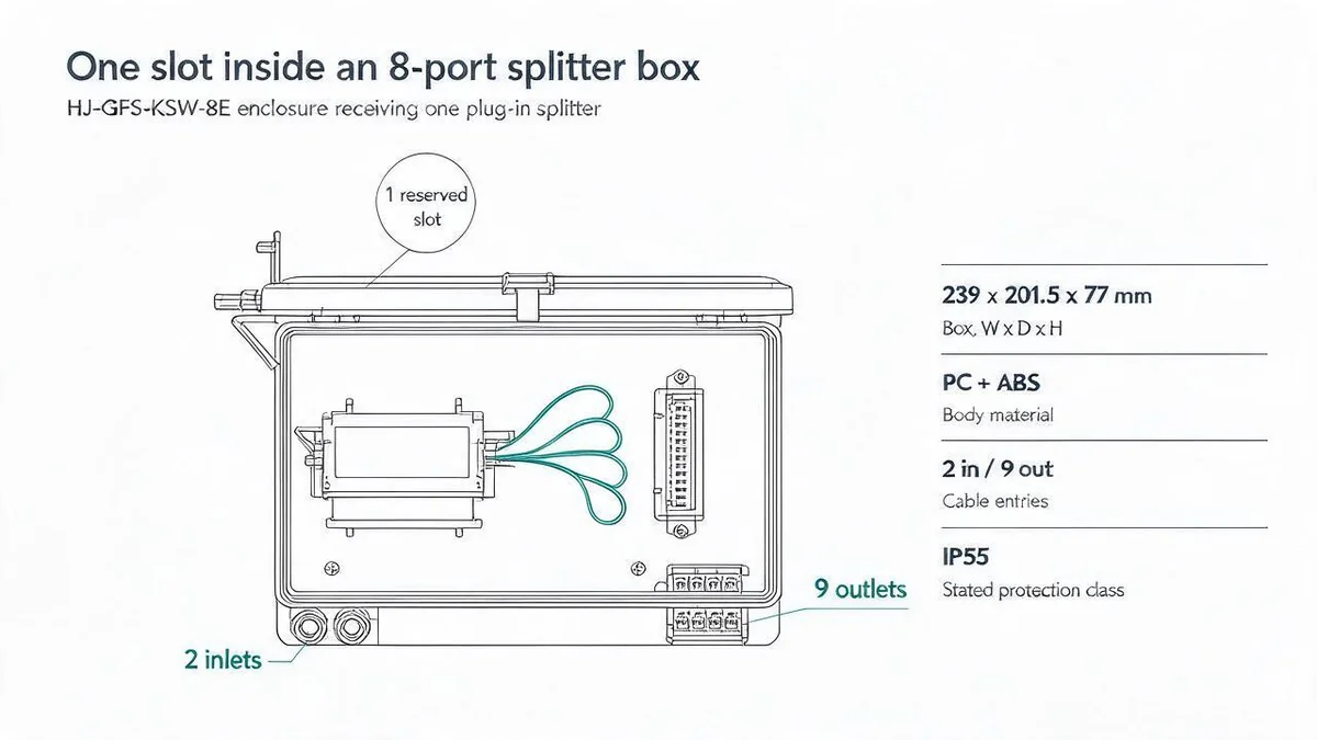
Three numbers in that specification are worth reading together. The page publishes only 1:4 and 1:8 as accepted ratios for this box, so a 1:16 module is outside its published range. At 1:8 the box has eight splitter outputs against nine outlets, and at 1:4 it fills only four of them. Which output or adapter each outlet serves is fixed by the cabinet drawing, not by the splitter data sheet, so the port plan should come from that drawing before pigtails and drop cables are cut.
The IP55 claim and what the IP code actually covers
The IP55 line on that page is the enclosure's stated protection class. Under IEC 60529, a degree of protection describes what an enclosure provides against access to hazardous parts, ingress of solid foreign objects and ingress of water, verified by standardized test methods. The dust numeral and the water numeral are separate tests, and water numeral 5 is the jet test run with a 6.3 mm nozzle.
The code therefore describes a tested enclosure; it does not by itself settle mounting height, cable-entry sealing or condensation inside the box. Those are site decisions, and the installer's gland work and lid condition affect the protection the enclosure actually delivers. Where the site is more exposed than the rating assumes, ask for the test basis behind the stated class and confirm the sealing detail in the cabinet drawing.
Mismatch risks that cause rework
Most wrong orders come from one of five gaps between the splitter data sheet and the enclosure it is meant for.
- The enclosure does not include the splitter. An ODN box listing "installable plug-in splitters 1:4, 1:8" is describing a slot standard, not a populated unit. The splitter, pigtails and adapters are separate order lines unless the configuration table says otherwise.
- Connector and adapter mismatch. Customizable SC or LC connectors on the splitter still need a matching adapter field in the cabinet or box. A plug-in module with SC connectors and a cabinet fitted for a different adapter interface will not terminate.
- A ratio the enclosure does not list. Each cabinet or box publishes the plug-in ratios it accepts, and those published ranges differ between models. Check that ratio against that model's own document, alongside its splitter slots, adapter positions and outlet count, instead of inferring a limit from any single number.
- Rack space and depth. A 1U subrack needs a free rack unit and clearance behind it. In a crowded rack, the 200 mm depth is the figure to check, not just the front height.
- A protection class read as a site guarantee. The IP code describes tests on an enclosure. Mounting height, cable sealing, condensation and service access remain design decisions for the site.
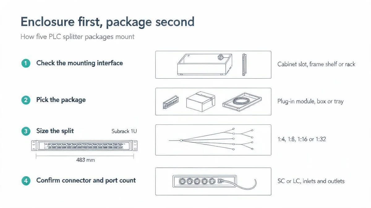
Decision order: enclosure first, package second
Run the four steps in this order and the package usually selects itself. Reversing them is what turns a splitter order into a cabinet modification.
- Read the mounting interface. Identify whether the target has a cassette slot defined by an operator specification, cabinet interior space for a compact box, a standard frame shelf, a 19-inch rack position, or none of these.
- Choose the package that interface accepts. Plug-in for a specified slot, box for cabinet interior, tray for a frame shelf, subrack for a rack unit, miniature tube only where the housing will be designed.
- Fix the split ratio, then check it against three enclosure numbers. Confirm the ratio appears in that model's published accepted ratios, that the splitter slots match, and that the adapter or outlet count can carry the live outputs. For 1xN splitters including connectors, the published maximum insertion loss rises from 7.4 dB at 1:4 to 10.5 dB at 1:8 and 13.8 dB at 1:16, so the ratio decision also sets the loss budget the link has to absorb.
- Match connector, adapter and pigtail. Confirm the connector type the splitter will be built with, the adapter field on the cabinet or box, the polish, and the pigtail form the installer will dress.
The sequence matters because each step narrows the next one. The cabinet interface is a field constraint that arrives with the enclosure and is expensive to change after delivery. Package choice, ratio and connector are specification lines on the splitter order, where changes are still cheap.
What to send with a splitter enquiry
A supplier can answer a package question in one round if the enquiry carries the enclosure, not just the ratio.
- The cabinet or box model, with the slot, shelf or cabinet-interior drawing and the port plan.
- Indoor or outdoor placement and the mounting method.
- The split ratio, and how many outputs are live at cutover.
- Connector and adapter type, including polish.
- Pigtail length and form, and the quantity per site.
- The protection requirement, and whether a test report is expected with the delivery.
With those in hand, the splitter can be quoted against a specific slot, shelf or rack position instead of against a general category name, and the connector set can be confirmed against the adapter field before anything is built.
——END——