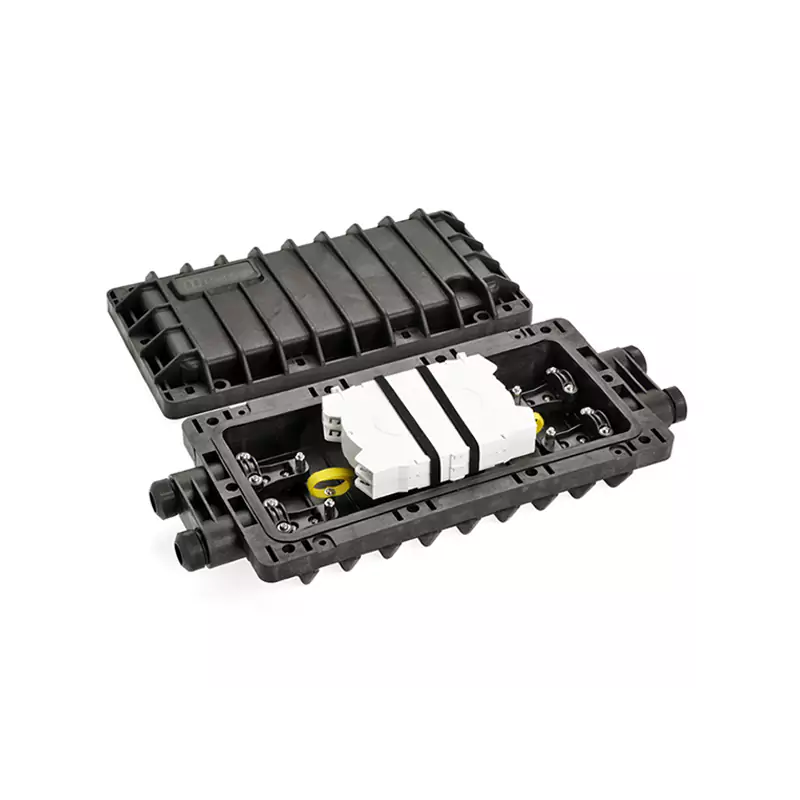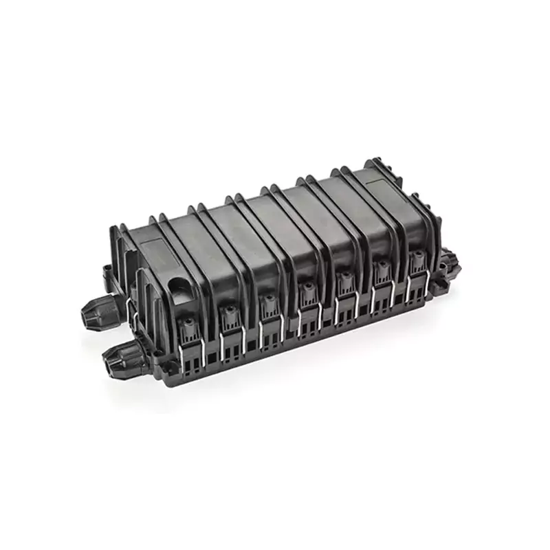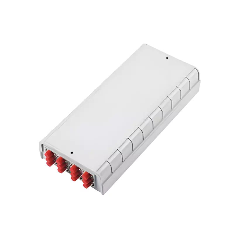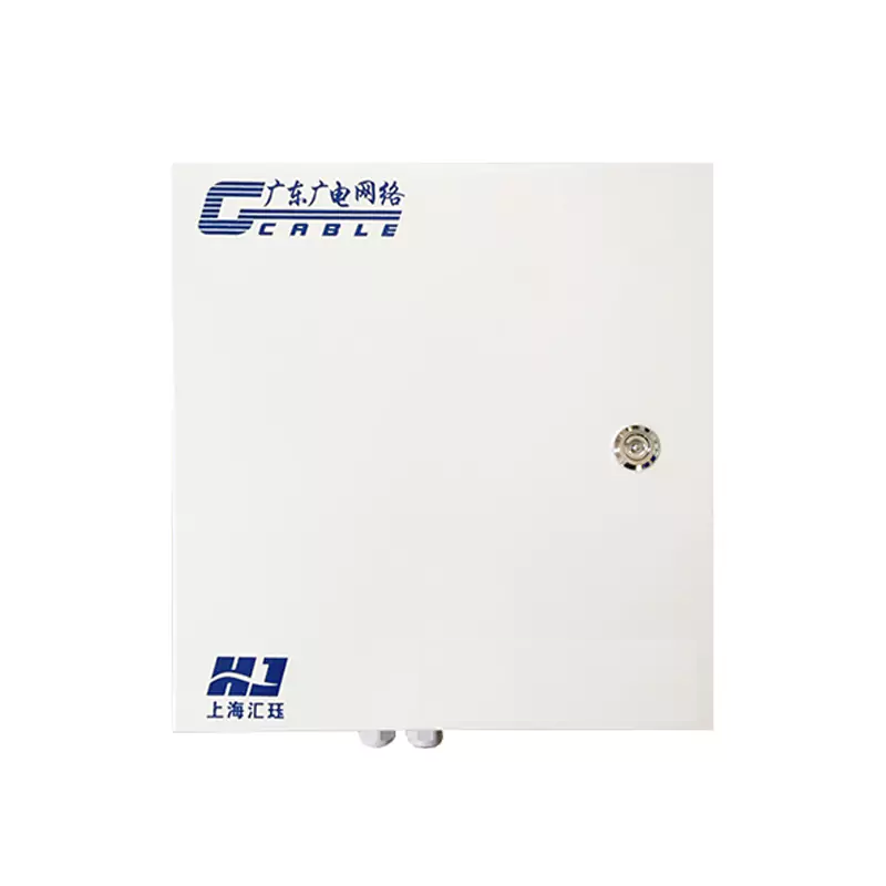
32-Core Metal Optical Splitter Box
32-core Metal Optical Splitter Box HJ-GFS-KJW-32C adopts a separate fusion-splicing and distribution structure, with fusion splicing and optical distribution functions.
Product Features
Meets the requirements for distribution and protection of 1~2 optical cables (Φ8~15mm) and terminal distribution of 4 plug-in type optical splitters (along with distribution pigtails or drop cables);
Adopts a sheet metal structure, made of galvanized sheet (stainless steel optional) with a thickness of 0.8~1.2mm;
Optical Splitter: Capable of installing plug-in type optical splitters (1:4, 1:8, 1:16, 1:32); Maximum core count: 32 cores;
Protection Class: IP55;
Equipped with a reliable fixing device for optical cables and drop cables;
The box can be equipped with a fiber parking position device and an optical cable pulling device;
The fiber distribution box adopts a hinged flap structure, enabling convenient and quick fiber fusion splicing and termination operations;
The box body adopts a sealed structure;
Technical Parameters
| Model | Product Dimensions | Weight | Material | Cable Inlet Holes |
| HJ-GFS-KJW-32C | 350*340*110mm | 3.2~4.3kg | Galvanized Sheet 1.0~1.2mm | 2 Inlets & 1 Hole |
| Product Configuration Table | |||||
| Serial No. | Name | Specification | Quantity | Unit | Remarks |
| 1 | Cabinet | 350*340*110mm | 1 | Set | Including internal structural components |
| 2 | Splitter Bracket | Flip-type | 1 | Set | 4 slots reserved |
| 3 | Optical Splitter | Plug-in SC | * | Set | Optional (1:4, 1:8, 1:16, 1:32) Maximum Quantity: 4 slots |
| 4 | Pigtail | Single-core SC | * | Piece | Optional (0.9mm pigtail, 2.0mm pigtail, drop cable available) |
| 5 | Fiber Splicing Tray Device | 12-core | 2 | Block | Maximum 2 blocks configurable |
| 6 | Heat Shrink Tube | Single-core heat shrink tube | 24 | Piece | |
| 7 | Fiber Protection Sleeve | 1 | Meter | ||
| 8 | Accessories | Installation accessories | 1 | Set | Standard configuration |
Solutions
We provide professional optical fiber communication solutions tailored to different industries and application scenarios.
FTTN (Fiber to the Node)
The FTTN (Fiber to the Node) solution involves laying optical fibers to node cabinets several miles away from users, then transmitting network signals to user terminals via traditional copper cables. It is an ideal choice for meeting the broadband upgrade needs of urban areas or communities, and is suitable for access requirements in small and medium-sized regions.
Application
Urban and Peri-Urban Areas
Major Residential Areas and Communities
FTTC (Fiber to the Curb)
FTTB (Fiber to the Building)
FTTH (Fiber to the Home)
FTTP (Fiber to the Premises)

Adapts to Multi-user Needs
For large buildings, providing fiber access throughout the entire building
Highly Reliable
Provides stable high-speed internet connections, meeting high-demand commercial and residential usage
Highly Scalable
Supports future expansion and flexible service distribution

Ultimate Access Speed
Fiber reaches the curb, closer to users, providing higher bandwidth and lower latency
Flexible Deployment
Adapts to flexible cabling needs in urban and densely populated areas
High Bandwidth Guarantee
Through fiber network connections, meeting high-bandwidth application needs such as HD video and cloud computing

Meet Diverse User Needs
Tailor full-building fiber access solutions for large-scale constructions
High Reliability
Deliver stable, high-speed internet connectivity to meet the demands of high-performance commercial and residential use.
Strong Scalability
Support future expansion and flexible service allocation
Ultra-high-speed Internet
Direct access to fiber networks, achieving gigabit-level bandwidth, supporting bandwidth-intensive applications such as HD, 4K video, VR/AR
High Stability
No electromagnetic interference, fiber connections ensure communication stability
Future Scalability
As demand grows, fiber networks can seamlessly expand to meet increasing bandwidth needs

Wide Coverage
Integrating FTTH and FTTB solutions to meet the needs of various customers including homes and enterprises
High Bandwidth Guarantee
Provides excellent network experience, supporting cloud applications, high-volume video transmission, etc.
One-stop Service
Comprehensively considers user scenarios, provides flexible fiber deployment solutions, ensuring seamless connectivity